To measure or not to measure that’s the question.
Introduction
This blog is an introduction to the Internet of Things (IoT), and will cover the technical aspects of working with digital-sensors and how they could be used in a library setting. I will work towards an interactive bookshelf that will spark the interest into browsing a bookshelf, and thus making a bookshelf less ‘dusty’. Although this blog is very technical I will try to inform a general audience about the possibilities that the Internet of Things has to offer. The IoT revolution depends on having access to cheap sensors that are able to measure things in the real world, combining output from these sensors enables new solutions that where previously impossible.
Overview
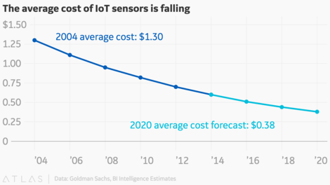
As the cost of sensors are dropping dramatically (Despite recent COVID hickups) libraries should invest some time and general understanding on how-to deploy these. The Internet of Things landscape is riddled with commercial companies that want to gather as much data as they can, while I think a library thrives on privacy. My advice for any library that want’s to deploy a massive IoT setup, please be transparent about it, involve your patrons, they have a right to know and might be interested in the subject as well.
During lockdown I had time to experiment with a lot of (bare-bone) IoT devices, and I will share my IoT setup here.
What’s in it for me
If you don’t have a technical background, some parts of this blog might be hard to understand, I suggest you skip all code parts, and read it anyway to get a little understanding of what all the buzz about Internet of Things is all about. Since the cost of the devices that are at the core of this revolution (microcontrollers and sensors) are now dirt-cheap, it’s hard to get devices without them, yes, even your toothbrush will be equipped with these kind of technologies. Often these devices will be labeled ‘smart’, what’s meant here is that they are connected to some company (via the Internet) that uses data generated by sensors, transmitted by microcontrollers to make some graphs or generate usage profiles of some kind, but be aware, the ‘smartness’ comes with a hefty privacy-toll. In the blog I will cover the basics of getting started with a ultrasonic range sensor a microcontroller and a Raspberry Pi and show different communication methods to access the sensor data. If your not familiar with Linux or Python, I suggest getting into the the basics, find a copy of Linux/Python for beginners from your local library, buy a minicomputer like a Raspberry Pi and get your hands dirty!

A good article about other experiments done inside a actual library with sensors appeared in code4lib Issue 38, 2017-10-18. Code4Lib Testing Three Types of Raspberry Pi People Counters. In this blog I will take different angle using the same kind of sensors, and explain why.
Let’s start with the definition IoT devices are. I’m a fan of Wikipedia so here is the obligatory quote:
The Internet of Things (IoT) describes physical objects (or groups of such objects), that are embedded with sensors, processing ability, software, and other technologies, and that connect and exchange data with other devices and systems over the Internet or other communications networks.
To further narrow down what this blog is about, the IoT industry is huge, there are roughly two top classes by which to divide the IoT world in, IIot and Iot. The extra I in IIot comes from Industry, in this domain the equipment used is more robust, accurate and secure then the equipment used at home. During my education I was exposed to the IIoT side of things, back then these where not even called IoT devices but Programmable Logic Controllers(PLC’s). The equipment we used in class was goes by the name of Adam. The idea’s behind PLC’s kindof evolved into IIoT, as these techniques where the driver behind the the third industrial revolution. Mayor companies like Siemens now brand their product as IIOT. For the home user a lot of stuff sold as IoT works out of the box, setup-procedures are super simple, mostly the device want’s to somehow get access to the Internet so you must give it access to your Wi-Fi network, and batta bing your device works. In this blog I will try to explain in detail how this works (Without sending your data to 3rd-parties), and how you can create your own IoT setup.
Let’s get technical
There are a lot of good resources on the Internet about how-to setup your own IoT landscape, so making the right choices is important. My weapon of choice for setting things up is Python, for it’s a very accessible programming language, also I like minimalistic solutions, so I won’t touch upon big IoT projects like NodeRed, HomeAassistant or how-to hookup IoT to the cloud.
Last warning, this a very DIY!
For microcontrollers there is a special Python distribution available for playing with these devices, MicroPython. I highly recommend this book: Programming with MicroPython, embedded programming with microcontrollers & Python by Nicholas H. Tollervey
Now that we’ve defined our programming language let’s talk hardware, and how you could setup your IoT experiments.
The general idea here is this:
Sensor -> Microcontroller -> Raspberry Pi
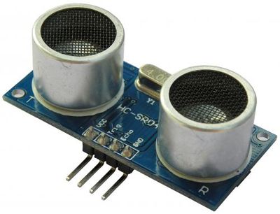
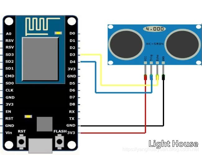
In this setup your sensor is always able to talk to the microcontroller, if you hookup sensors to your Raspberry Pi you might experience lags while accessing the data (If your Pi is for example running background processs, or an software update). Using the MicroPython distribution you are running the microcontroller dedicated in embedded real-time mode, this will ensure no lags will happen, there are no big background processes running on the controller. The ultrasonic range sensor I will use later on is not super stable, and during testing I noticed that connecting a ultrasonic range sensor directly to the Raspberry Pi resulted in a lot of false measurements, this is due to the lack of a real-time kernel. In embedded systems the kernel is designed to maintain low latency, consistent response time, and determinism. The Raspberry Pi operating system is not designed for this, thus resulting in false measurements. Using a microcontroller to handle the sensor data ensures the data accuracy and improves stability of the system. The microcontroller also offers more flexibility in the way it transmits data upstream.
Sensors
Let’s start with the sensor part. There are a lot of things you can measure with sensors, ranging from simple switches to water-levels, radar sensors, CO2 sensors etc.
To explore a wide range of possibilities I suggest getting a sensor-kit, something like this:
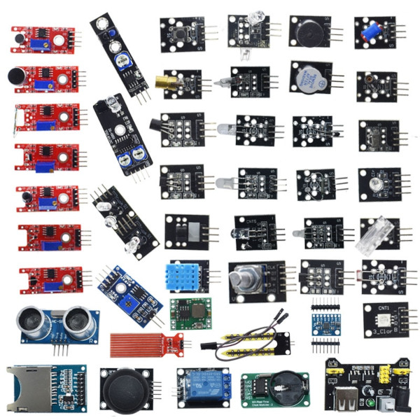
Available via retailers, for example AliExpress or DealExtreme.
Most of these sensor have been tested with MicroPython and tutorials on how-to connect and operate these are widely available, as well as source code. MicroPython itself has good online documentation. In order to attach the sensors to a ESP8266 you will need some wire, I recommend getting some DuPont wire (Female to Female).
Many kind of sensors sense the real-world and send digital information right back to the microcontroller. In order to make sense of what the sensor is measuring often a calculation step is needed, or some logic to enhance what the sensor is reporting back to the Raspberry Pi. Most (basic) sensors require three wires running from the microcontroller to the sensor, these are power, ground and a data-line (sensor output).
Here is a small MicroPython example for reading a HCSR04 ultrasonic range sensor.
Microcontrollers
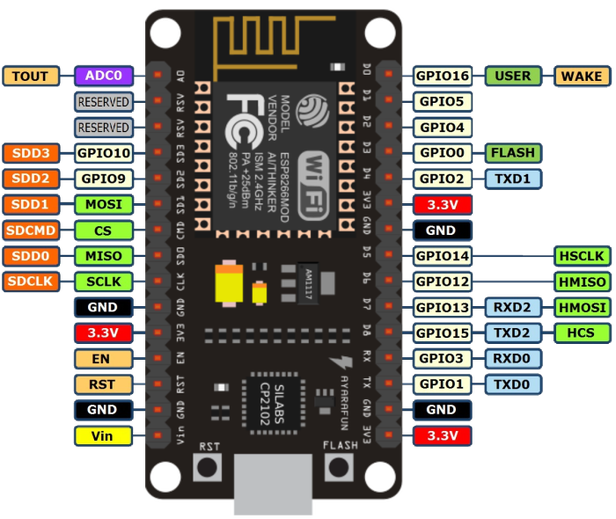
I’ve tested several devices for this purpose, and the thing I like best and is the ESP8266 used in the NodeMCU. For all experiments I used Raspberry Pi OS Lite and Python3 to communicate with the ESP8266 microcontroller, but this can also be done from any system with a USB-port and a UNIX like operating system.
According to Wikipedia:
The ESP8266 is a low-cost Wi-Fi microchip, with a full TCP/IP stack and microcontroller capability, produced by Espressif Systems in Shanghai, China.
There are several ways of communicating with the microcontroller, once deployed.
- Via serial communication using the USB-connection.
- Via Wi-Fi.
- By other means, like SPI, GSM, LORA, Bluetooth, ect. (Not covered in this blog).
The first step is to erase and flash new firmware onto the ESP8266 device. Firmware is the software that runs on the microcontroller once it is powered, and it’s called firmware because you are not able to modify it once written to the chip without interrupting the whole system.
First install the required tools, firmware and create an initial empty boot.py file.
# Tools for putting firmware on the ESP8266
sudo apt install -y picocom esptool

# Tools for putting files on the ESP8266
sudo pip3 install adafruit-ampy

# We'll work in this project directory
mkdir esp_8266
cd esp_8266
touch boot.py # For now make an empty boot.py, later you can fill this with code to read and transmit sensor data.

# This is the firmware.
wget 'http://micropython.org/resources/firmware/esp8266-20210902-v1.17.bin'

# These are some handy external libraries.
curl -s https://raw.githubusercontent.com/micropython/micropython-lib/master/micropython/urllib.urequest/urllib/urequest.py > ureq.py
curl -s https://raw.githubusercontent.com/andrey-git/micropython-hcsr04/master/hcsr04.py > hcsr04.py
Once the microcontroller boots, it will run the firmware (Which contains a version of MicroPython) and execute the boot.py file. In this file we will put the logic needed to read data from the attached sensors.
Note that esptool may be outdated, if you get weird errors during invocation, use:
sudo apt remove -y esptool
sudo pip3 install esptool
See this page for more info on the MicroPython firmware, and the Github page for the esptool.
Attach your ESP8266 to your USB-port of choice, and verify the connection by identifying the chip:
esptool chip_id
If all is well the output will look something like this:
esptool.py v3.2-dev
Found 1 serial ports
Serial port /dev/ttyUSB0
Connecting....
Detecting chip type... ESP8266
Chip is ESP8266EX
Features: WiFi
Crystal is 26MHz
MAC: e8:db:48:ad:97:fe
Uploading stub...
Running stub...
Stub running...
Chip ID: 0x00ad97fd
Hard resetting via RTS pin...
Next is creating a little flash & disaster recovery script:
#!/usr/bin/env bash

esptool --port /dev/ttyUSB0 erase_flash
esptool --port /dev/ttyUSB0 --baud 115200 write_flash --flash_size=detect 0 esp8266-20210902-v1.17.bin

# ampy can be used to interact with the file-system on the ESP8266.
ampy  -p /dev/ttyUSB0 put boot.py
# The boot.py file is invoked once the ESP8266 boots.

# Some external libraries are required.
ampy  -p /dev/ttyUSB0 put hcsr04.py
ampy  -p /dev/ttyUSB0 mkdir urequests
ampy  -p /dev/ttyUSB0 put ureq.py /urequests/__init__.py

# Verify that code is transmitted and written.
ampy  -p /dev/ttyUSB0 get boot.py
ampy  -p /dev/ttyUSB0 ls

picocom --baud 115200 /dev/ttyUSB0 # This will create a connection to your ESP, to quit press CTRL-a, CTRL-x
Whenever you can’t get readings from your ESP8266, don’t hesitate to flash it again.
USB
Using the serial connection you will be able te transfer data very reliable, but not as fast as over Wi-Fi (2.7 mega bits/sec) according to this load tesing an esp8266. But for low-latency and high reliability/security data transfer a serial connection works just fine, I’ve tested the Python library ‘pyserial’ to get readings directly from the USB-port (cable length <5M) and this works like a charm.
Installing pyserial:
sudo pip3 install pyserial
Code for serial communication with the ESP8266:
#!/usr/bin/env python3

import serial

ser = serial.Serial('/dev/ttyUSB0', 115200)
while True:
    print(ser.readline().decode("utf-8").strip())
Please note the port, which by default will be ‘/dev/ttyUSB0’ under Debian, it might be different on your OS, if unsure check the output of:
sudo dmesg
By default the ESP8266 turns on a Wi-Fi Access Point (AP), if you want to use a serial connection it’s wise to turn the Wi-Fi completely using the following code: (You can add this to the boot.py file using your favorite editor.)
import network
sta_if = network.WLAN(network.STA_IF)
sta_if.active(False)
ap_if = network.WLAN(network.AP_IF)
ap_if.active(False)
An AP is normally used to connect to, you can do nice things with this option, like update the firmware and run a web-server on the ESP8266, but for this blog I will not explore these scenarios.
I prefer to let the ESP8266 send data, rather then having the Raspberry Pi poll all the ESP8266’s deployed, so I recommend turning off the access point (which will by default show up something like ‘MicroPython-2884894’ in your Wi-Fi network list). In order to do this, the last 2 lines of the code-snippet above will have to run first, before starting the main loop, add them to the boot.py file.
The final result, reading the Ultrasonic range sensor will look something like this:
import time
import network
import hcsr04

sta_if = network.WLAN(network.STA_IF)
sta_if.active(False)
ap_if = network.WLAN(network.AP_IF)
ap_if.active(False)

hc = hcsr04.HCSR04(5, 4)

while True:
    try:
        distance_cm = hc.distance_cm()
        print("Left sensor", distance_cm)
        time.sleep(0.1)
    except:
        pass
Wi-Fi
The example below shows you how-to transer data from the ESP8266 to a mosquitto server using the mqtt protocol. The example measures the distance to an object using the a ultrasonic range sensor. To be able to run this, I will explain howto setup a Raspberry Pi as a (WiFi) IoT-gateway later in this blog.
from umqtt.simple import MQTTClient

import machine
import network
import time
import ujson
import hcsr04

ap = network.WLAN(network.AP_IF)
ap.active(False)

config = {"dns": "8.8.8.8",
          "gateway": "192.168.0.1",
          "ip": "192.168.0.4",
          "mosquito_server": '192.168.0.1',
          "nodeId": "shelf_right",
          "subnet": "255.255.255.0",
          "wifiPass": "passwd",
          "wifiSSID": "iot_gateway"}

def wifi_connect(config):
    print('connecting to %s' % config["wifiSSID"])
    sta = network.WLAN(network.STA_IF)
    sta.active(True)

    sta.ifconfig((config['ip'],
                  config['subnet'],
                  config['gateway'],
                  config['dns']))

    sta.connect(config['wifiSSID'],
                config['wifiPass'])
    time.sleep(1)
    print('connected to %s' % config["wifiSSID"])

def main(server=config['mosquito_server'], hc):
    client = MQTTClient('umqtt_client', server)
    client.set_callback(pub_range_right)
    client.connect()

    loop = True

    while loop:
        try:
            distance_cm = hc.distance_cm()
            client.publish(b"distance_right", ("%i" % distance_cm).encode("utf-8"))
        except:
            loop = False
    c.disconnect()

if __name__ == "__main__":
    hc = hcsr04.HCSR04(5, 4)
    wifi_connect(config)
    error = 0

    while True:
        if error > 1:
            wifi_connect(config)
            error = 0
        try:
            main(config, hc)
        except:
            error += 1
Raspberry Pi
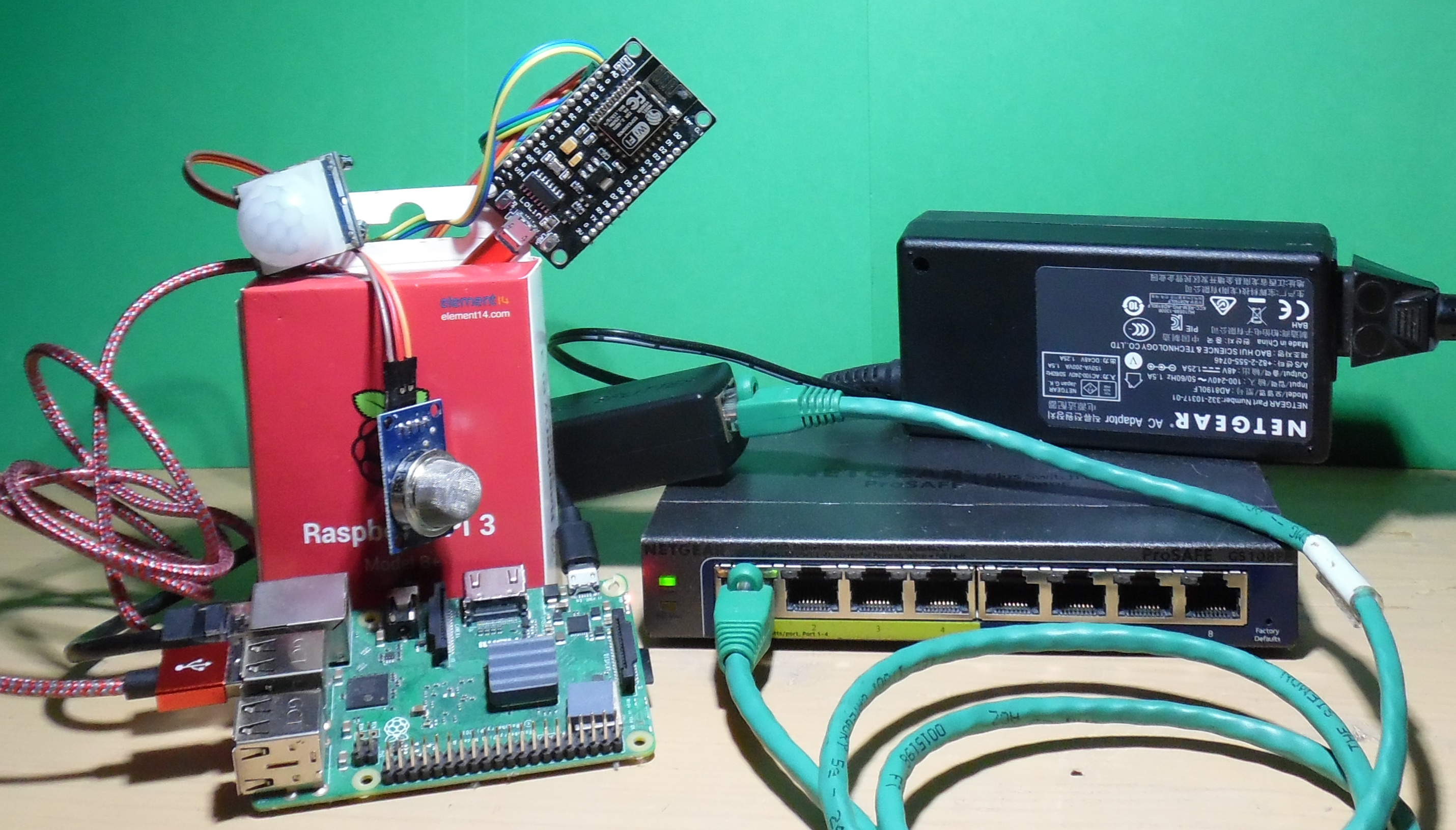
I recommend getting a Raspberry Pi 3 Model B or better. The tremendous speed of this device will allow you to do some amazing visualizations of your sensor data, muchas gracias Eben Upton (YT). For my test setup I used a Netgear ProSAFE GS108OE as Power Over Ethernet (POE) switch to power the Raspberry Pi, the Raspberry Pi will in it’s turn power the ESP8266 microcontroller, and the ESP8266 will power the sensors. The final components, a network-cable and a POE-splitter will split power and Ethernet signal needed to power up the Raspberry.
So the power will flow like this:
POE-switch -> Network cable -> POE-splitter -> Raspberry Pi -> USB micro cable -> ESP8266 -> DuPont wire -> Sensors
The final setup will look something like the image shown below:
The information gathered from the sensors will travels the opposite way like this:
USB: POE-switch <- Network cable <- POE-splitter <- Raspberry Pi <- USB micro cable <- ESP8266 <- DuPont wire <- Sensors
Wi-Fi: POE-switch <- Network cable <- POE-splitter <- Raspberry Pi ))) Wi-Fi ((( ESP8266 <- DuPont wire <- Sensors
By creating a setup like this you will be able to separate all IoT related traffic from the rest of your network. The data will be processed on the Raspberry Pi, from your internal network you will only need access to the Raspberry Pi’s web-interface to look at the stats generated by accumulating sensor data. You could also hookup a monitor directly to the Raspberry Pi and create a real-time display using something like pygame.
Whilst many solutions I’ve studied on the Internet propagate the idea of exposing your microcontrollers directly to the Internet, I think this is a bad idea from a security and privacy standpoint. Sure it has some advantages, but these are outweighed by my concerns of getting hacked or data fed into some cloud infra. An other option I’ve seen is connecting a ESP8266 via Wi-Fi to a smartphone, which is as dangerous as it gets. The ESP8266 itself is a perfect tool for deauthing Wi-Fi networks, but that’s a subject on it’s own.
Wi-Fi
If you have many sensors and ESP8266 around a Wi-Fi access point is a great solution for connection all the devices.
Use the following commands on the Raspberry Pi to turn it into an IoT access point / gateway:
sudo apt install -y hostapd tmux
sudo apt install -y mosquitto mosquitto-dev
# To change the IP-number to bind to create a default.conf here: /etc/mosquitto/conf.d
echo "listener 1883 192.168.0.1" >> /etc/mosquitto/conf.d/default.conf
Add this line to your /etc/rc.local
tmux new-session -d -s wifi 'while true; do rfkill unblock 0; ifconfig wlan0 192.168.0.1; hostapd -f /home/pi/hostapd.log -i wlan0 /etc/hostapd/hostapd.conf; sleep 1; done'
Contents of /etc/hostapd/hostapd.conf
driver=nl80211
ctrl_interface=/var/run/hostapd
ctrl_interface_group=0
beacon_int=100
auth_algs=1
wpa_key_mgmt=WPA-PSK
ssid=iot_gateway
channel=1
hw_mode=g
wpa_passphrase=ChangeMe
interface=wlan0
wpa=2
wpa_pairwise=CCMP
country_code=nl
Your IoT clients must set their IP manually to the 192.168.0.1-255 range in order to talk to the mosquitto server.
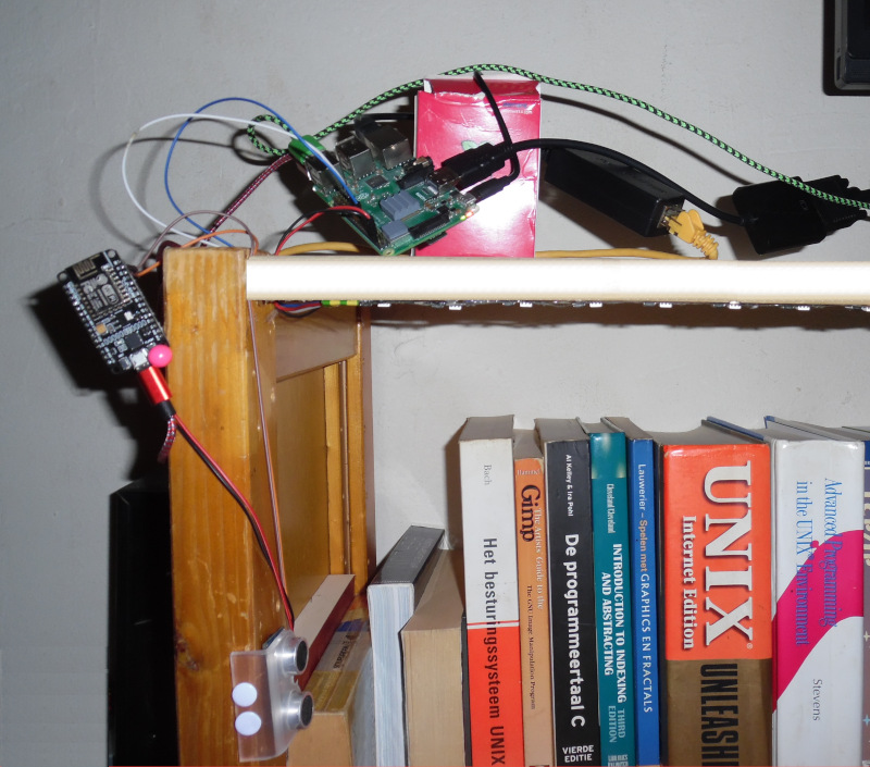
Bookshelf demo
I’ve done some work on an interactive bookshelf as the (beta)final product. The first step is to create an index of all the books on the shelf. Next align the index of the books to physical location of the books (using a ultrasonic range sensor), and add a RGB-ledstrip above the books. Once a book is fetched from the shelf, by using the position information you can now show additional data about the book, and trigger other actions.
Creating a book-index
In order to create an index of the bookshelf I’ve created a file (booklist.txt) containing ISBN-13 numbers, and used the python package isbnlib to fetch metadata (like author and publish-year).
#!/usr/bin/env python3

import json
import isbnlib #  pip3 install isbnlib

# cat boolist.txt
# 9781938377006
# 9789057644771
# 9789021290270

book_list = []

with open('booklist.txt', 'r') as fp:
    data = fp.read()
    for line in data.split('\n'):
        if not line.strip():
            break
        isbn = line.strip()
        book = isbnlib.meta(isbn)
        book_list.append(book)

with open('booklist.json', 'w') as fh:
    fh.write(json.dumps(book_list))
I’ve manualy added some extra metadata like “Image” and “Abstract”.
Calibration

For calibration I’ve used a little pygame interface, the ESP’s are using a USB connection in this example. Because in my setup two ultrasonic range sensors are aligned up, they will allways interfere (from picking up the wrong signals) and will spit out semi-random data. During calibration if a book is fetched, it will noise-cancel out the two interfering sensors. If we get a stable reading 8 times in a row, we will know the position of the book. The position information on the book can later be used to trigger action’s when the book is fetched from the shelf.
The code for calibration is available on github.
After Calibration you will have the extra element ‘pos’ available in the json file (booklist_alignd.json).
[{
  "Authors" : [
     "Kief Morris"
  ],
  "pos" : [
     35,
     37
  ],
  "Language" : "en",
  "Year" : "2016",
  "ISBN-13" : "9781491924358",
  "Title" : "Infrastructure As Code - Managing Servers In The Cloud",
  "Publisher" : "O'Reilly Media"
},
{
  "Language" : "en",
  "Title" : "Beyond The Basic Stuff With Python - Best Practices For Writing Clean Code",
  "Publisher" : "No Starch Press",
  "Year" : "2020",
  "ISBN-13" : "9781593279660",
  "Authors" : [
     "Al Sweigart"
  ],
  "pos" : [
     38,
     34
  ]
}]
Demo
For the final demo I will use the same setup, and fetch books from the shelf, this allows me to show the metadata about the book I’ve fetched directly onto the screen. For text-to-speech I’m using espeak, this makes your shelf very accessible for people with a visual handicap. You could get creative and display other stats then I did, like how many times was the book fetched, and reading time, or if you like play some music that goes well with the book you fetched.
The code for the interactive bookshelf is available on github, share and enjoy!